|
193_DOC1.pdf |
;)
;)
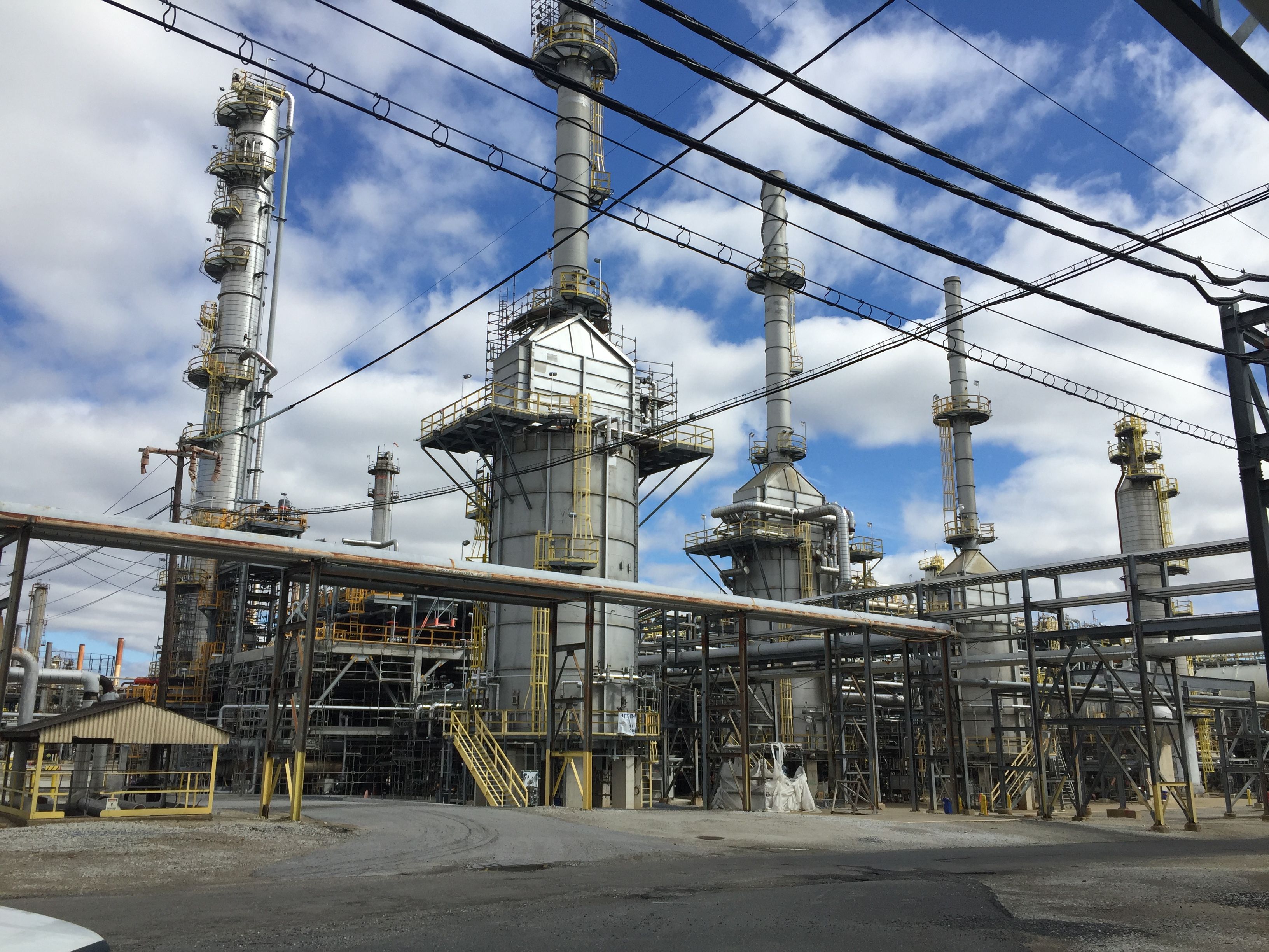
60,000 BPD LSG Unit Tier 3
Category : Refineries Manufacturer : ExxonMobil SCANfining / AXENS Prime - G+ Plant Type : Refinery Capacity : 60,000 Barrels Per Day
Technical Drawings/Spec Sheets
ADDITIONAL DESCRIPTION
Tier 3 Unit (10 PPM)
Built in 2004; Tier 3 Revamp in 2019 and was never operated.
Technology: ExxonMobil SCANfining / AXENS Prime - G+
Unit Capacity: 60,000 BPD
Operating Pressure: 310
Design Pressure: 455
Operating Temp: 540
Design Temp: 850
General
870 is an Exxon/Mobile Licensed SCANfining unit that upgrades FCC gasoline by catalytically hydrodesulfurizing sulfur compounds in the feed to meet low sulfur gasoline specifications. It was built in the early 2000 to meet the new gasoline sulfur specifications. It was designed specifically to limited the saturation of olefins which reduces the product quality by reducing octane.
Process
870 utilizes two parallel trains of Cold Feed/Effluent exchangers, Diolefin Saturators, Hot Feed/Effluent exchangers, SCANfining Reactors and Reactor Effluent coolers. The Fractionation and Treating sections are common to both trains.
The feed to 870 is 65,000 bpd of debutanized full range cat gasoline. The feed enters the Feed Surge Drum and is regulated by two flow controllers (one in each of the two trains) downstream of the Reactor Charge Pumps. The Reactor Charge Pump discharge stream enters the Feed Filters to remove particulate matter present in the feed. The filtered feed is split equally and is mixed with a portion of the recycled treated gas, H2. The gasoline feed and treated gas mixture are preheated in the Cold Feed/Effluent Exchangers to the required inlet temperature for the Diolefin Saturators. The Diolefin Saturators are mixed-phase trickle bed reactors utilizing KF-840 or equivalent catalyst. KF-840 is a NiMo hydrotreating catalyst. The operating conditions of the Diolefin Saturator are maintained such that a minimum of 60% of the feed diolefins are saturated without initiating hydrodesulfurization and olefin saturation reactions.
The effluent from the Diolefin Saturator is combined with the bulk of the treat gas and heated further in the Hot Feed/Effluent Exchangers to completely vaporize it before entering the SCANfining Reactor. In the SCANfining Reactors, hydrodesulfurization (HDS), hydrodenitrogenation (HDN), and olefin saturation (OSAT) reactions occur over ExxonMobil's proprietary RT-225 catalyst. The inlet temperature to the SCANfining Reactors is controlled by controlling the firing in the Reactor Effluent Heater
The products from the two parallel SCANfining Reactors, including hydrocarbons, H2, H2S, and NH3, are re-combined and then sent to the Reactor Effluent Heater. The combined reactor effluent streams are superheated in the Reactor Effluent Heater to provide sufficient duty and temperature driving force to achieve the required Diolefin Saturator and SCANfining Reactor inlet temperatures. They are cooled in the Reactor Effluent Cooler before entering the Reactor Effluent Separator. Make-up hydrogen is added upstream of the Reactor Effluent Separator to control unit pressure.
Recycle gas) from the Reactor Effluent Separator is Amine treated to remove H2S and then recycled using a motor drive compressor back to the reactor system. The Liquid product from the Separator is sent to the Stripping Section. The Product Stripper has a fired heater reboiler and removes H2S and light-ends. It is designed to achieve a low sulfur gasoline product H2S concentration of less than 1 wppm.
The low sulfur gasoline product is cooled before being sent offsite to gasoline blending.
------------------------------------------------------------------------------------------------------------------------------------------------------
870 Tier 3 (Axen Prime G+ Addition)
A 70 LSG Tier 3 project was underway to increase the unit capacity and operating severity in the existing Low Sulfur Gasoline (LSG) unit, Unit 870. The LSG Unit capacity was to increase from 65 MBPD to a nominal 76 MBPD. Philadelphia Energy Solutions (PES) was preparing to do final tie-ins in October 2019 (never occurred) to modify the existing 870 to meet the Environmental Protection Agency¿ (EPA) Tier 3 Gasoline Sulfur Standard, which limits the gasoline pool sulfur average to 10 ppmw.
870 Tier 3 (Axen Prime G+ Addition)
All major equipment had been delivered and was installed on the unit except for final piping tie-ins, internal modification to the unit surge drum, and conversion of the primary SHU Reactors to an p-flow design, which were all to be completed during the October planned Turnaround.
The primary change to the existing LSG unit was to the integration of Axens PrimeG+ technology. The unit would continue to pretreat the cat. naphtha feed in the primary SHU Reactors (formerly referred to as Diolefin Saturators). However, by installing a new total reflux splitter column, the reduced sulfur light naphtha is taken as a side draw product, leaving only the heavy naphtha to be treated in the HDS Reactors (formerly referred to as SCANfining). As the light naphtha carries the majority of the olefins, treating only the heavy naphtha allows for a more severe desulfurization in the HDS reactors, while limiting octane loss.
Furthermore, in order to reduce the size of the new splitter column and associated equipment, the unit feed was to be split to the tower. As the 1232 Heavy Cat. Naphtha (HCN) is much less olefinic, it would be segregated from the 1232 Light Cat. Naphtha (LCN) and the 868 Full Range Cat. Naphtha (FRCN). The two feed streams will be treated in parallel SHU reactor trains before entering the Naphtha Splitter column, the LCN/FRCN entering near the middle, while the HCN flows directly to the tower sump. Reduced treat gas rates in the SHU reactors results in lower space velocities, in order to meet Axens required LHSV, the existing SHU reactors were to be modified to operate in an upflow configuration.
Project Basis and Discussion
The Axens Split Feed Case would utilize a new splitter tower; however, to reduce the tower cost, the unit feed would be split such that the 1232 HCN will be treated separately in its own SHU reactor train (70R-01B) before entering the sump of the splitter tower. The 1232 LCN and 868 FRCN would be combined and treated in a separate SHU reactor train (70R-01A) and enter the splitter tower above tray 20. This option results in slightly less light naphtha product draw, however, significantly reducing the size of the tower and associated equipment (reboiler, condenser, etc.).
Currently the 1232 HCN and LCN are piped together at 1232 before routing to 870. In order to split the unit feed, a new line would need to be installed between the two units. As there is currently a bottleneck in the OSBL product flow leaving 870 to the 1232 unit, it was decided that a new 10 line would be installed and used as the product line, while the existing 8 product line would be repurposed as the new 1232 HCN feed line. The benefits of this new line could be seen today, therefore this new product line is part of an early construction package. By splitting the feeds, additional surge capacity is required for the new 1232 HCN feed. To accomplish this, the existing 70V-01 Feed Drum will be modified to include an internal baffle, creating two hydrocarbon compartments with a common vapor space. A new pump and feed filter will be installed as the 1232 HCN feed pump to the existing SHU reactor.
With the splitter column being a low-pressure point in the middle of the existing hydrotreater, all unconverted hydrogen, treat gas, and off gas from the SHU reaction will be lost from the hydrotreater system. In order to limit the amount of gas that will be sent to the 868 Wet Gas Compressor, the gas leaving the splitter is routed to the 870 fuel gas system to provide additional gas. Per environmental standards, the total fuel gas/off gas blend will be monitored locally by a new CEMS H2S analyzer.
Furthermore, as the treat gas is lost from the SHU system, Axens design minimizes the amount of gas used in the system. Compared to today operation, the Axens scheme will result in an almost liquid filled reactor; while the reactor currently sees about 55% vapor. With this dramatic decrease in volume, in order overcome the low space velocity in the SHU reactors, both reactors must be repiped to operate in upflow mode, with a new inlet upflow distributor. Once operating in the upflow configuration and split flow, the reactor trains now have a limited turndown. As the HCN flow is lower than the LCN/FRCN flow, the SHU (R-01B) reactor only has a turndown of approximately 90%. In order to maintain adequate flow through the unit, the ormally no flow product recirculation line will be utilized to supplement the B train. To minimize the amount of dioelfins in the HDS reactors, the product recirculation is taken before the addition of the lighter splitter side draw product.
Can't find what you need? Click HERE to contact us.
We sell Complete Plants and Process Equipment on a Worldwide Scale. LCEC has locations around the globe, which gives us the ability to acquire entire Complete Plants for relocation. If you need Ammonia, Nitric Acid, Urea, Hydrogen, Methanol or any other Process Complete Plant, our strategic positioning can help you fill your need. Please contact us for more information. Let LCEC find the Complete Plant or Process Equipment you require.