;)
;)
;)
;)
Category : Featured Plants Manufacturer : ** Plant Type : Hydrogen Capacity : 53 MMSCFD
Operating Pressure: 20barg at Reformer inlet
Technology Provider: UHDE (HMU unit design), KTI (reformer design), Shell (ADIP-x design)
Purity: 97mol% (Dry) at maximum unit capacity
Year Commissioned: 1986
The Refining NZ Hydrogen Manufacturing Unit contains the following key processes and equipment:
Feed Gas Pre-Treatment via a Caustic Wash System: This system removes H2S and Chlorides from Hydrogen rich feed gas, upstream of the Feed purification system.
Butane and Tops Feed systems: Two separate liquid feed systems are provided, one designed to pressurise and vapourise butane at up to 300t/d and supply to the Feed purification system, the other designed to pressurise and vapourise light naphtha at up to 170t/d to the Feed purification system.
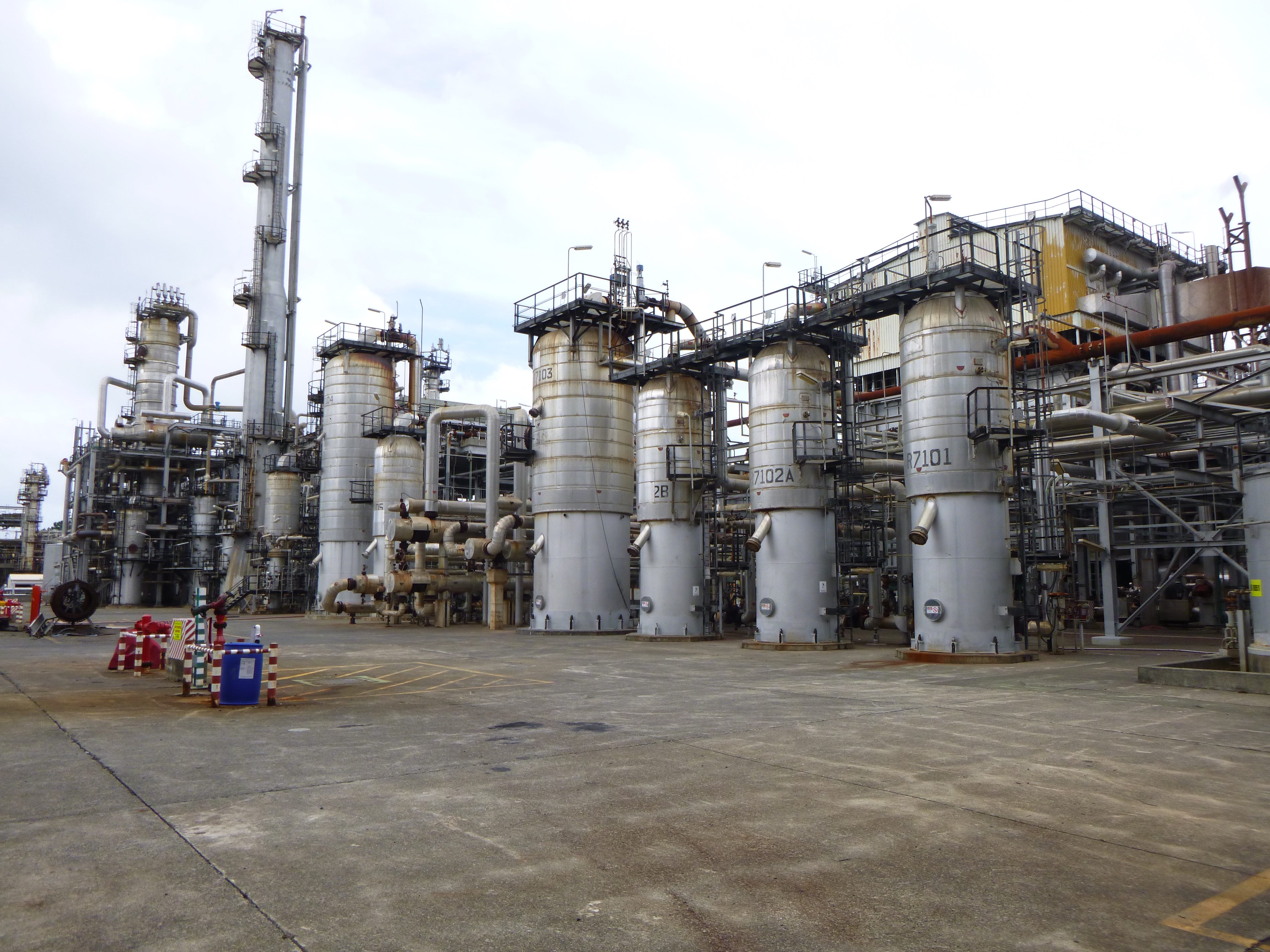
Reformer Feed Purification System: Multiple reactor system (R7101, R7102A/B) to remove H2S down to a level of 0.5ppmwt in the Reformer feed, suitable for desulphurisation of hydrogen rich feed gas, butane and light naphtha.
Steam Reformer: A top fired reformer designed by KTI, combines feed gas and steam and reforms into hydrogen rich process gas, targeting a methane slip of 2-3%mol (dry) at normal operating conditions.
-The Reformer tube metallurgy is (24Cr/24Ni/Nb). The maximum design temperature for the F7101 tubes is 950°C.
-F7101 has 315 tubes (125.4mm O.D; 97.2mm ID ×11.557m) arranged in banks of 7 rows of 45 tubes, and has had no tube failures.
-The reformed gas from each row of tubes is collected in a refractory lined header with an incoloy sleeve to prevent erosion and silica migration. Each header is equipped with a temperature indicator to enable the furnace heat distribution to be balanced. The individual gas collection headers and common header were replaced in 2018, and in near new condition.
-The reformer is a top fired design utilising 144 burners arranged in 8 rows of 18 burners.
-Flue gas heat is recovered in multiple convection bank heat exchangers.
--Shock tubes in convection bank coil F7101A heat circulating BFW to saturated steam which is then superheated in convection bank coils F7101E/C/B before mixing with the hydrocarbon feed in M7101 and then onto Reformer F7101.
--Feed preheat is provided by Banks D and F.
--Combustion air preheat is supplied by convection bank G.
-The reformer furnace is a balanced draft design, with combustion air provided by combustion air blower K7102 and flue gases removed via induced draft flue gas blower K7103.
Steam Generation System: HP steam (~45-50barg) is generated from heat recovery from the process gas exiting the reformer and the flue gas waste heat recovery system. The steam generation system includes a steam drum V7105, multiple heat exchangers F7101A, B, C, E and E7104, E7106, and multiple desuperheaters J7101/2/3.
Water Gas Shift Section: A reaction section including both a High temperature shift (R7103) and Low Temperature shift (R7104) reactor, reducing the CO content and increasing the H2 content in the process gas stream. CO content of the process gas is typically reduced to below 0.25mol% at the outlet of the Low Temperature Shift reactor, at start of run catalyst conditions.
CO2 Removal Section: CO2 from the process gas system is removed via a Shell designed ADIP-X system (Activated MDEA), which includes CO2 absorber C7104 and ADIP-X Regenerator C7106. The ADIP-X system is heat integrated with the main process system, with process gas (condensing steam) providing the reboil duty for C7106. CO2 is removed down to trace levels in the process gas (less than 0.1mol%, typically less than 100ppm).
Methanation: The final step in the process gas clean-up is to convert any remaining CO and CO2 (approx. 0.2 – 0.6%mol) to methane across R7105, the methanation reactor. This methanation step is required at Refining NZ to ensure only trace amounts of CO and CO2 (200ppm max) are sent to the Hydrocracker.
Condensate Stripping Section: Steam condensed in the process is directed to a condensate stripper C7108 to remove any entrained/dissolved gases (hydrogen, CO, CO2, methane and methanol) prior to recycling the condensate to the refinery condensate recovery system. CO2 and Methanol levels are typically reduced to below 5ppm.
Nitrogen Circulation Facilities: Nitrogen circulation facilities (compression, heating, cooling) is used during start-up to slowly heat up a number of section within the process unit and also during shutdown to cool down and hydrocarbon free a number of systems within the hydrogen manufacturing unit.
Can't find what you need? Click HERE to contact us.
We sell Complete Plants and Process Equipment on a Worldwide Scale. LCEC has locations around the globe, which gives us the ability to acquire entire Complete Plants for relocation. If you need Ammonia, Nitric Acid, Urea, Hydrogen, Methanol or any other Process Complete Plant, our strategic positioning can help you fill your need. Please contact us for more information. Let LCEC find the Complete Plant or Process Equipment you require.